floppy disk drive- 5.25 inch. google#motherboard connector to FDD#
- Kentek 8 Inch 8" 4 Pin Molex 5.25 Male to 4 Pin 3.5 Floppy Drive FDD Female & 4 Pin Molex 5.25 Female Y-Splitter M/F IDE DC Internal Computer PC Power Cable Adapter Cord
- Basic & Major Parts of Motherboard and their Functions
- CablesOnline 36 inch Universal Floppy Drive Ribbon Cable for 3.5 or 5.25in Drives, (FF-002)
- FDD connector vs. Floppy cable
- What Is an FDD Connector?
- How to install a floppy disk drive
- Floppy drive help and support
- Floppy cable
- How to troubleshoot floppy disk drive issues
- Cleaning the computer and its components
- How to fix a 3.5" floppy detected as 5.25" floppy
- What is Floppy Disk Drive | Types of Floppy Disk | How Does a Floppy Disk Store Data
- How to Read a Floppy Disk on a Modern PC or Mac
- 6.3 FDD Interface and Cabling
- Remove and Install a Floppy Drive
- Floppy Disk Drive: connector
- Floppy Drive 4-Pin Power Connector Pinout
- Floppy Disk Drive Pinout FDD
- Install The Hard Drive And Floppy Drive
- FDD connector
- Floppy-disk controller
- Where the heck is Pin 1? Here are five ways to find it
- More on Motherboards
- All about the various PC power supply cables and connectors
- Powering a floppy drive
- How to install FDD
- Back to Basics - The Motherboard
- Floppy Disk Drive
- Berg connector
- the four-pin polarized Berg connectors used to connect 3½-inch floppy disk drive units to the power supply unit, usually referred to as simply a "floppy power connector", but often also referred to as LP4. This connector has a 2.50 mm (0.098 in) pitch (not 2.54 mm).
- the two-pin Berg connectors used to connect the front panel lights, turbo switch, and reset button to the motherboard.
- the two-pin Berg connectors used as jumpers for motherboard configuration.
- Floppy Disk Drive Parts and Working [Explained]
- 34-pin male connector on Motherboard. As you can see in the figure below, there is a 34 pin male connector on the motherboard which is assigned for floppy disk drive connection.
- FDD interface Cable. A 34-pin cable is required for connectivity to the floppy disk drive. With one cable you can connect two floppy disk drives. The Drive that connects at the twisted end becomes A-Drive and the drive at the other end turns into B-Drive.
- “TIP:The red wire is the No.1 wire and make sure to connect it to the No.1 of connectors on both FDD and motherboard”
- “Warning: If the LED on the front side of FDD glows permanently it means the cable is connected in reverse direction.”
- Power Connector. The power is supplied to FDD on a 4-pin male connector as shown in the figure.
- Connecting 5.25" floppy drive to Dell B110 desktop
- Installing a Power Supply.
- Floppy Cables
- Installing a FDD
- To install one FDD in a system, standard practice is to jumper that drive as the second drive (DS1/DS2) and connect it to the end connector. Alternatively, you can jumper the drive as the first drive (DS0/DS1) and connect it to the middle connector. Either method allows the system to see that drive as A:. If your drive cable has only two connectors, jumper the drive as the second drive (DS1/DS2). Note that most current 3.5-inch FDDs are set permanently as the second drive, and have no jumper to allow changing that assignment. Such drives work properly with a two-connector data cable, and should be connected to the end connector on a three-position data cable.
- To install two FDDs in a system, jumper both drives as the second drive (DS1/DS2). Connect the A: drive to the end connector and the B: drive to the middle connector. (Note that the chipsets used in many recent systems support only one FDD.)
- Sometimes, cable constraints (length or available connector types) make it impossible to configure the drives as you want them. If this happens, check BIOS Setup to see if it allows you to exchange A: and B:, overriding the drive designations made by DS jumper settings and cable position.
- Installation of Floppy Disk Drive
- How to build an external 5.25" floppy drive
- Guide on how to connect a 3.5
- Mitsumi FDD & USB Card Reader
- Connector for connecting FDD. Solving the problem of connecting a floppy disk drive to a modern computer. Emulation using USB Flash Источник: https://newtravelers.ru/en/d-link/razem-dlya-podklyucheniya-fdd-reshenie-problemy-podklyucheniya-floppi-diskovoda-k-sovremennomu-kompyuteru.html
- Plugable USB 2.0 Digital Microscope with Flexible Arm Observation Stand Compatible with Windows, Mac, Linux (2MP, 250x Magnification)
- 6 Writing Tips to Build a Branding Strategy for Your Startup
- Getting my old as dirt 5.25" floppy drive working on a modern computer
buy this adapter to meet my old 5.25inch FDD...
Parts of Motherboard Parts of Motherboard. What is Motherboard? Motherboard is a PCB (Printed Circuit Board) with different hardware components on it.
buy this cable.

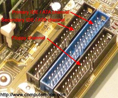
The floppy channel, FDD header, or floppy connection is where the floppy drive connects to the computer motherboard. In the picture below, is an example of a motherboard with two IDE connections and a floppy channel connector..
Finally, the standard PC floppy drive connector contains 34-pin holes. Below is a listing of each of these pins and their descriptions.
What Is the FDD Connector? FDD stands for floppy disk drive. Although most computers no longer use floppy drives, the FDD connector is still present on many motherboards. The FDD connector contains 34-pins, and uses a FDD ribbon cable to connect to a 3 ½" floppy disk drive. Identify this cable by the twist between the first and second set of connectors, which allocates the drive at the end of the cable as FDD A, and the drive in the middle as FDD B.
Install Open the computer case and connect the floppy drive to the computer using screws or a bracket..
Floppy drive help and support.
A floppy cable is a ribbon cable found in PC's that allow one or more floppy disk drives to connect to a computer. In the illustration, is a visual example of what a floppy cable may look like and where each end of connectors connect. As shown, this cable allows a desktop computer to have two floppy drives connected to one floppy controller..
The floppy channel, FDD header, or floppy connection is where the floppy drive connects to the computer motherboard. In the picture below, is an example of a motherboard with two IDE connections and a floppy channel connector.
If you are experiencing issues with the floppy drive in your computer, review the troubleshooting options below to try and resolve the problem..
This is a paragraph.
If you insert a 3.5" floppy disk into your computer and it's recognized as a 5.25" floppy disk, follow these steps to fix the problem.
not very good.
Remember floppies? Back in the day, they were essential. Eventually, they were replaced, and floppy disk drives vanished from new computers. Here’s how to access a vintage 3.5- or 5.25-inch floppy disk on a modern Windows PC or Mac.
Controller PC-class systems used a separate FDD controller card. XT- and AT-class systems and some early 386s used a combination HDD/FDD controller card. Current systems use an embedded FDD controller. These controllers differ only in their maximum data rate, which determines the FDD types they support. Early controllers run at 250 Kb/s, which supports only 360 KB 5.25-inch FDDs and 720 KB 3.5-inch FDDs. Later controllers run at 500 Kb/s, which supports any standard FDD, or at 1 Mb/s, which is required for 2.88 MB 3.5-inch FDDs. Run BIOS Setup to determine which FDD types a given system supports..
good video to watch...
Although the capacity of a Floppy Disk is very small for saving data, it can still be useful to create a boot disk for fixing operating system problems, or when flashing the BIOS.
Floppy Disk Drive Connector on Motherboard You may not have a Floppy Disk Drive connector on a newer motherboard but an older motherboard may well have one as shown in the photograph above. The connector is similar but slightly smaller than an IDE connector and usually marked as FDD. Two Floppy Disk Drives can be controlled by the single FDD connector which is connected to the Floppy Disk Drive by a ribbon cable.
The ribbon cable has two connectors at one end for each Floppy Disk Drive and a connector at the other end which plugs into the motherboard. The computer can distinguish between the two drives because there is a twist in the ribbon cable. The Floppy Disk Drives become Drive A: and Drive B:
The ribbon cable usually has a red line running down one side which should align with pin 1 on the motherboard connector and pin 1 on the Floppy Disk Drive.
The power cable has a 4 pin connector which will fit only one way into the Floppy Disk Drive.
Rear of Floppy Disk Drive with Data & Power connectors.

The floppy drive 4-pin power supply connector is the standard floppy drive power connector in computers today.
The power connector itself is a Berg connector, sometimes referred to as a Mini-Molex connector.
Below is the complete pinout table for the standard floppy drive 4-pin peripheral power connector as of Version 2.2 of the ATX Specification (PDF)..
see the picture on the page...
Floppy Disk Drive Cable The table below provides the Personal Computer Drive A Pinout for either the 3 1/2 or 5 1/4 floppy drive. The cable uses a 34-pin IDC connector [requiring a 34-pin device header], and a 34-pin flat ribbon cable [IDC Definition]. The connector size differ between the two drive types, with the 5.25" drives requiring a larger connector. The 3.5" floppy drive format is the size in common use, and the common cable in general use will not have the 5.25" drive connectors. A common cable name which accepts both the 3.5" and 5.25" drives may be termed a universal cable. The pin out differences for the B drive is shown after the table. The twist in the cable causes the pin out difference, and is used to indicate which drive is the 'A' drive..

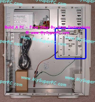
The Antec KS282 comes with a drive cage that makes floppy drive and hard drive installation a little easier. The idea is that the drive cage can be removed from the computer case, the drives mounted inside the drive cage, and then the drive cage put back inside the computer case. This makes it a little easier to get to both sides of the drive while inserting the mounting screws. Here is the location of the drive cage..
FDD (Floppy Drive Disk) header or connector is where the Floppy disk connects through a Floppy Drive cable. Floppy drive were not common today though it is still being used by some. It evolves from a floppy drive cable into a USB type..
A floppy-disk controller (FDC) is a special-purpose chip and associated disk controller circuitry that directs and controls reading from and writing to a computer's floppy disk drive (FDD). This article contains concepts common to FDCs based on the NEC µPD765 and Intel 8272A or 82072A and their descendants, as used in the IBM PC and compatibles from the 1980s and 1990s. The concepts may or may not be applicable to, or illustrative of, other controllers or architectures.
So there you are, with a dangling ribbon cable and a question. Where's Pin 1? In this Daily Feature, Ken Dwight gives you five methods for finding a pin in a haystack..
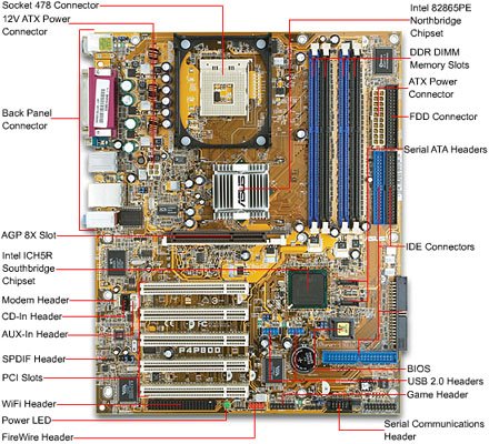
Overview: In this first image we can see the rear connectors. This is what you see when you look at the back of your computer. These were covered on the 'The Computer' page of this site. This motherboard was pretty typical in 2005. Newer motherboards are a bit different and use different connectors but this example is still useful. .
floppy disk drive power cable here is the 4-pin wire for FDD power connector:

the big picture is as below:

I need to power a floppy drive for a project. Currently, I have an ATX power supply powering it, but any five volt source will do, so I'm going to be switching to something smaller. The issue is, I don't know how to connect to the floppy power pins. Here is an image of how it looks:.
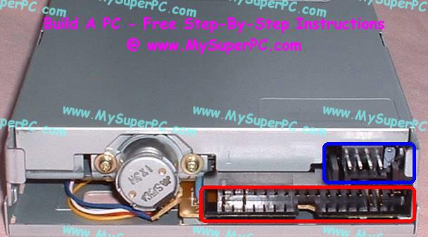
"The black connector on the left hand side is the floppy disk connector. It is different from the IDE connector and uses a different cable. The small white connector on the right hand side is the power connector for the floppy drive. Figure 1 and 2 below shows what a floppy drive cable and floppy drive power connector looks like."*.
Now the fun really begins as we start looking at the bits of the PC that you normally never see, and we'll begin with the system motherboard. The motherboard, also called the mainboard, is the large printed circuit board which is the elecronic hub of your PC. Not only does this circuit board host the Central Processing Unit, or CPU, which is the brains of the computer, it also either hosts additional plug in process cards or has features that can come on plug-in cards actually built into the motherboard itself. More on this in a minute..
The ribbon cable has two connectors at one end for each Floppy Disk Drive and a connector at the other end which plugs into the motherboard. The computer can distinguish between the two drives because there is a twist in the ribbon cable. The Floppy Disk Drives become Drive A: and Drive B:

You may not have a Floppy Disk Drive connector on a newer motherboard but an older motherboard may well have one as shown in the photograph above. The connector is similar but slightly smaller than an IDE connector and usually marked as FDD. Two Floppy Disk Drives can be controlled by the single FDD connector which is connected to the Floppy Disk Drive by a ribbon cable.
The ribbon cable has two connectors at one end for each Floppy Disk Drive and a connector at the other end which plugs into the motherboard. The computer can distinguish between the two drives because there is a twist in the ribbon cable. The Floppy Disk Drives become Drive A: and Drive B:
The ribbon cable usually has a red line running down one side which should align with pin 1 on the motherboard connector and pin 1 on the Floppy Disk Drive.
The power cable has a 4 pin connector which will fit only one way into the Floppy Disk Drive.
Berg connector is a brand of electrical connector used in computer hardware. Berg connectors are manufactured by Berg Electronics Corporation of St. Louis, Missouri, now part of Amphenol.
Rear side of 3½-inch floppy drive. Berg connector for power is shown on the left; data cable on right.

Berg connectors have a 2.54 mm (0.100 in) pitch, pins are 0.64 mm (0.025 in) square, and usually come as single or double row connectors. Many types of Berg connectors exist. Some of the more familiar ones used in IBM PC compatibles are:
Floppy drive power connector The power connector on the 3½-inch floppy drive, informally known as "the Berg connector", is 2.50 mm pitch (distance from center to center of pins).


The power cable from the ATX power supply consists of 20 AWG wire to a 4-pin female connector.[1] The plastic connector housing is TE Connectivity / AMP 171822-4 with female metal contact pins are choice of TE Connectivity / AMP 170204-* or 170262-*, where * is 1 or 2 or 4.[2][3]
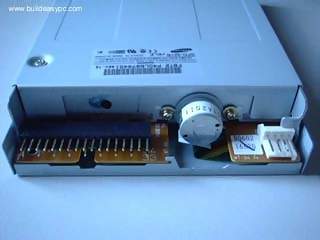
Floppy Disk Drive Connection in Computer. the rear side of FDD is as below:


I connected my old 3.5" drive to the IDE port on the B110 motherboard, and was able to use it just fine. Then connected my 5.25" drive, but it seems the BIOS only supports 3.5", and Windows XP is not able to read the disk.
Any suggestions? Do I need a special driver to make the 5.25" floppy work? If yes, where can I find it?
FDD cable:

DELL motherboard map:

First place your power supply at the back of your computer case. Standard power supply should have their fan toward the outside of the case. You will have to tighten your power supply to the case with 4 screws.

plug into FDD power connector into FDD :

Floppy drive cables look a lot like IDE cables except that they are a little narrower, have only 34 conductors, and have a twist at the end of the cable that attaches to the drives. They may have from two to five connectors: one to attach to the motherboard, and as many as four drive connectors, only two of which can be used at a time..

Installing an FDD in all but the newest systems is straightforward. Note, however, that some cases designed to accept FlexATX motherboards have only one externally accessible 5.25-inch drive bay, intended to accept a CD or DVD drive. This is because FlexATX systems are intended to boot from CD and so eliminate "legacy" connectors, including the FDD. That means if you intend to install an FDD in a FlexATX system, you'll need a case with two or more externally accessible drive bays (assuming you also want to install an optical drive and/or tape drive in the system), and you'll need to buy a separate PCI card that provides an FDD interface because FlexATX and other "legacy-reduced" and "legacy-free" motherboards do not provide an embedded FDD interface..
FlexATX motherboards also fit standard ATX cases, so installing the FlexATX motherboard in a standard ATX case eliminates the drive bay problem, although not the lack of an FDD interface. If you really need an FDD in a system, we recommend using a motherboard that provides an embedded FDD interface.
Use the following rules when installing FDDs:
I put the cable the correct way round, with the twisted end into the floppy drive, and then when I started the PC nothing happened, I have since tried another cable and still nothing, this now has me stumped! I know they only connect in the slot one way round, and I'm sure the power cables are connected properly. But I don't know what you mean by 'Pin Zero' and 'Pin 1'..


An important note:
Have fun finding the drivers for this. No motherboard after 1998 will support 5.25" disk drives. At least the operating systems don't. I have personally used a 5.25" disk drive to flash bios, however, Win XP, 2000, 7, don't work with floppies. They will recognize they went in the drive, but will not write or read..
Did you change the setting in the pre-boot CMOS for the first A floppy or second B floppy drive from "None" to something like "1.2 mb, 5.25''? And put the 1.2 MB drive on the correct cable connector, where A is on the end of the cable after the twist and B before the twist?
If connecting only one floppy it should be the first A.
Guide to hook up a 3.5" pc drive to your Amstrad CPC 6128 or 664 (For non-techy people like me).
The Mitsumi 7-in 1 Card Reader/Writer combines different memory card standards and floppy disk in one drive! It features a USB 2.0 interface for the Flash Card reader for easy installation! Whether you have a CompactFlash, Memory Stick, SmartMedia, Multimedia, or Secure Digital card, you can be sure that your data will transfer easily to your computer.
Connecting drives Drive for flexible disks is installed in the computer case. To connect to a system board on which the FDD connector is always available (NGMD, a flexible magnetic disk drive), a 34-core flat cable is used. Источник: https://newtravelers.ru/en/d-link/razem-dlya-podklyucheniya-fdd-reshenie-problemy-podklyucheniya-floppi-diskovoda-k-sovremennomu-kompyuteru.html
This is a paragraph.
Recent years have seen the advent of startups. Besides the regular restaurants, factories, and laboratories that have been springing up for a few decades, the new wave of startups is.
very good note:So I recently made a purchase on Amazon to put together an adapter for my 5.25" floppy drive. However, when I received the package today, I realized that the cable I ordered wasn't an IDE cable, but rather IDC34. This meant that my PCIe to IDE adapter(which I tested with an older drive and is working) would ultimately do nothing. Would it be possible to find a similar device for IDC34? I have PCIe, PCI, and SATA ports available..
No comments:
Post a Comment